DIY Project: Simracing Laptimer with 4-inch VoCore screen
There’s nothing better for a simracer than small functional gadgets that also visually enhance the rig. The simracing laptimer presented here does just that and, as a small and simple DIY project, is also ideal for beginners in the DIY world of simracing.
Project as a remix
The project presented here is a remix of the Vbox LapTimer RaceLogic (VoCore 4in) by AtoMic09, which was uploaded to Thingiverse under the Creative Commons – Attribution – Non-Commercial – Share Alike licence. The type of USB connection and the mounting of the VoCore screen have been changed, which no longer requires any additional mounting material.
The modified print files for the project can be found here:
List of parts
A 4-inch VoCore screen in combination with a micro USB socket was chosen for the realisation of the project, so that no soldering is required for this project, nor are there any problems with the signal quality of the VoCore screen, which tends to be a little tricky with hand-soldered cables. Then there are just four M3x12mm cylinder screws and matching nuts. Depending on the selection and source of the parts, the total cost is around €50-100:
- VoCore 4 Inch (Micro-USB) (3D-Simgear* | USB-C VoCore)
- Delock Cable USB 2.0 Micro-B female panel-mount (Amazon* | Delock)
- 4*M3x12mm cylinder head bolts
- 4*M3 nuts
- Optional: Cable ties
- Optional hot glue gun (Amazon*)
7% 3D-Simgear Gutscheincode / Coupon code: simracingpc
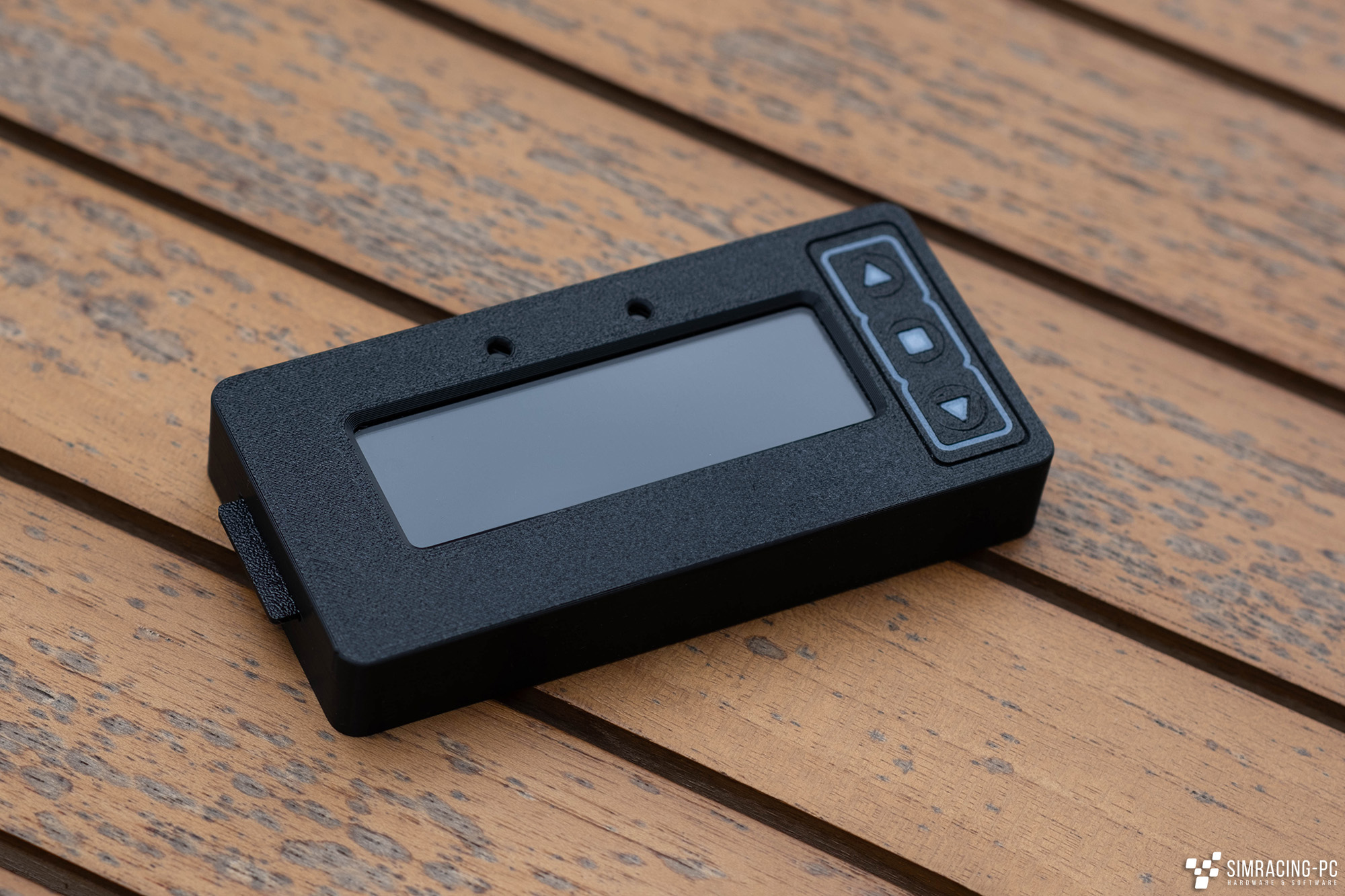
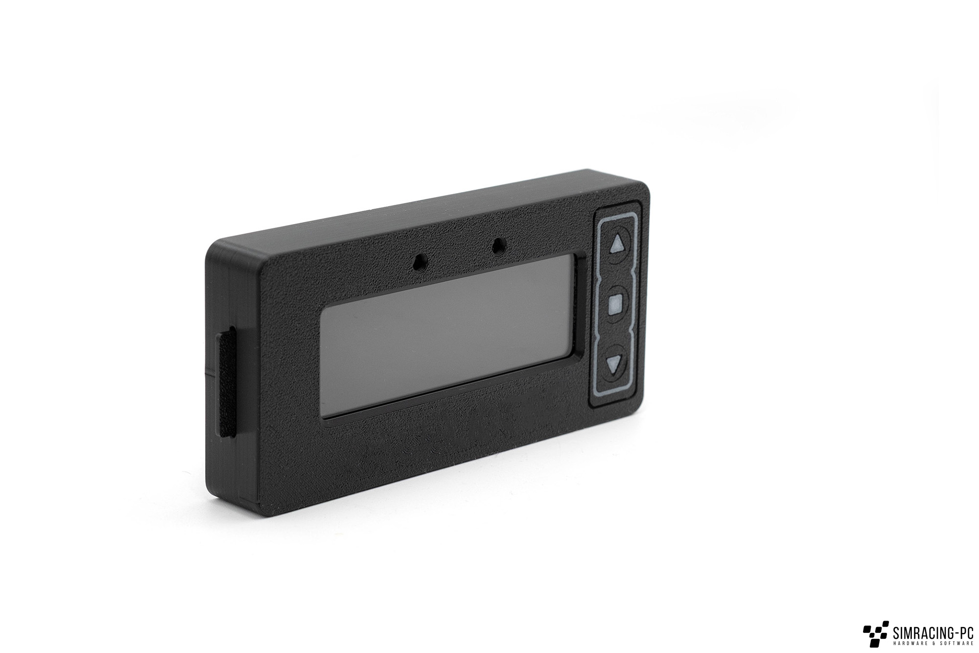
Housing (3D printed)
As you would expect, the housing of the Laptimer was produced using a 3D printer and consists of three parts.
- Front with two-colour structure. Here, the details of the buttons (without function, just for the look) were coloured with the help of Bambu Studio and then printed in multiple colours. Alternatively, the corresponding area can also be painted by hand or printed separately. For the latter, manual adjustment of the .stl file is necessary. There are approaches for this in the original project.
- Holder with integrated “SD card”. If a little more space is required, the bars of the slot for the ribbon cable of the VoCore screen can be cut off.
- Back
All parts can be printed without support and the total printing time is approx. 2-4 hours, depending on the printer. A layer thickness of 0.2 mm, 20 % infill and 3 layers each for the top and bottom as well as the print walls were selected.
Assembly
Assembly is carried out quickly. It requires the following steps:
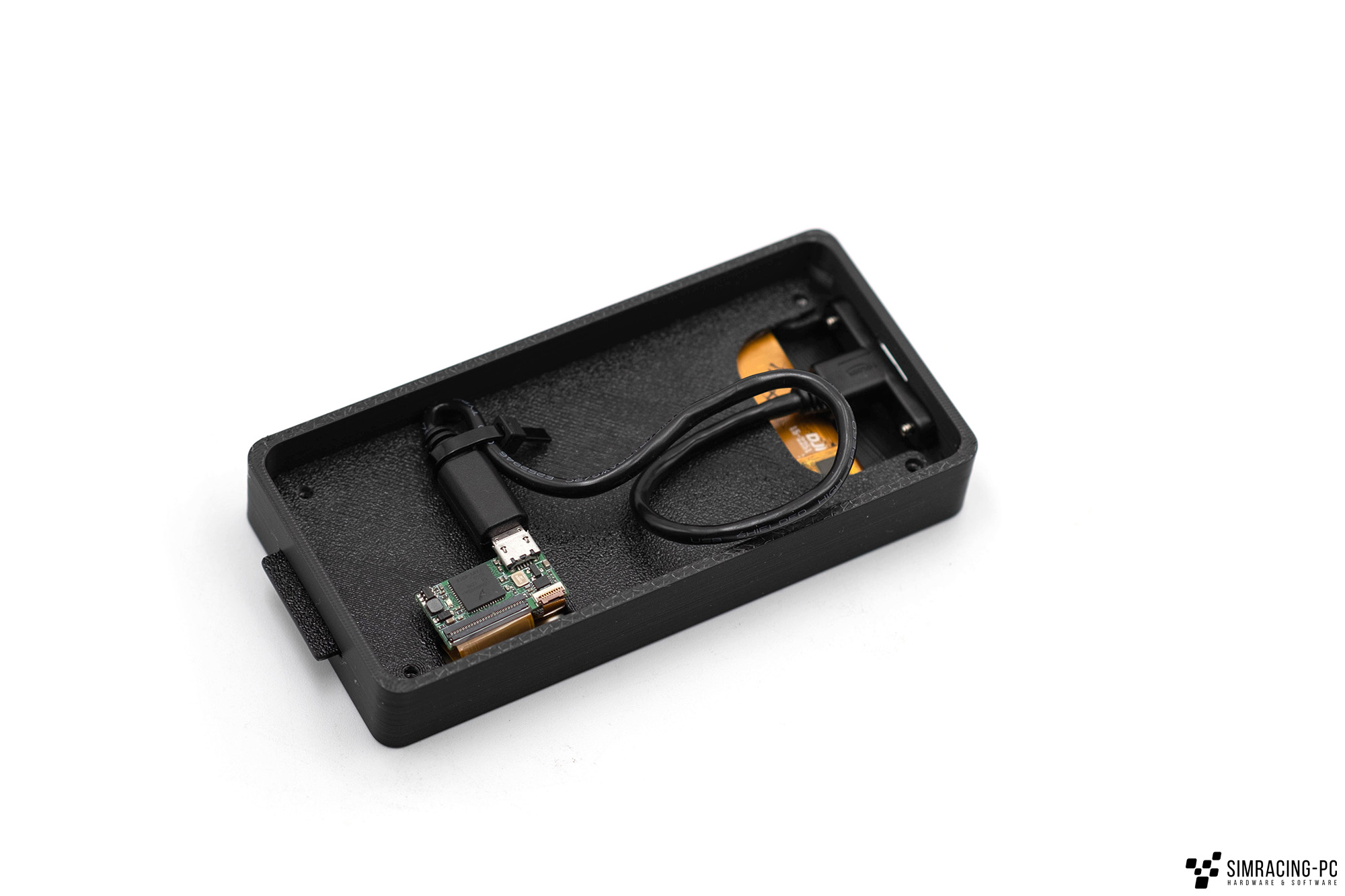
- Position the front panel with the top facing downwards
- Insert the four M3 nuts into the recesses provided.
- Insert the VoCore screen into the position provided (see photo for alignment).
- Slide the holder sideways into the recess of the “SD card”. Note: To avoid damaging the ribbon cable, the VoCore display and holder can also be brought into the correct position in relation to each other before installation.
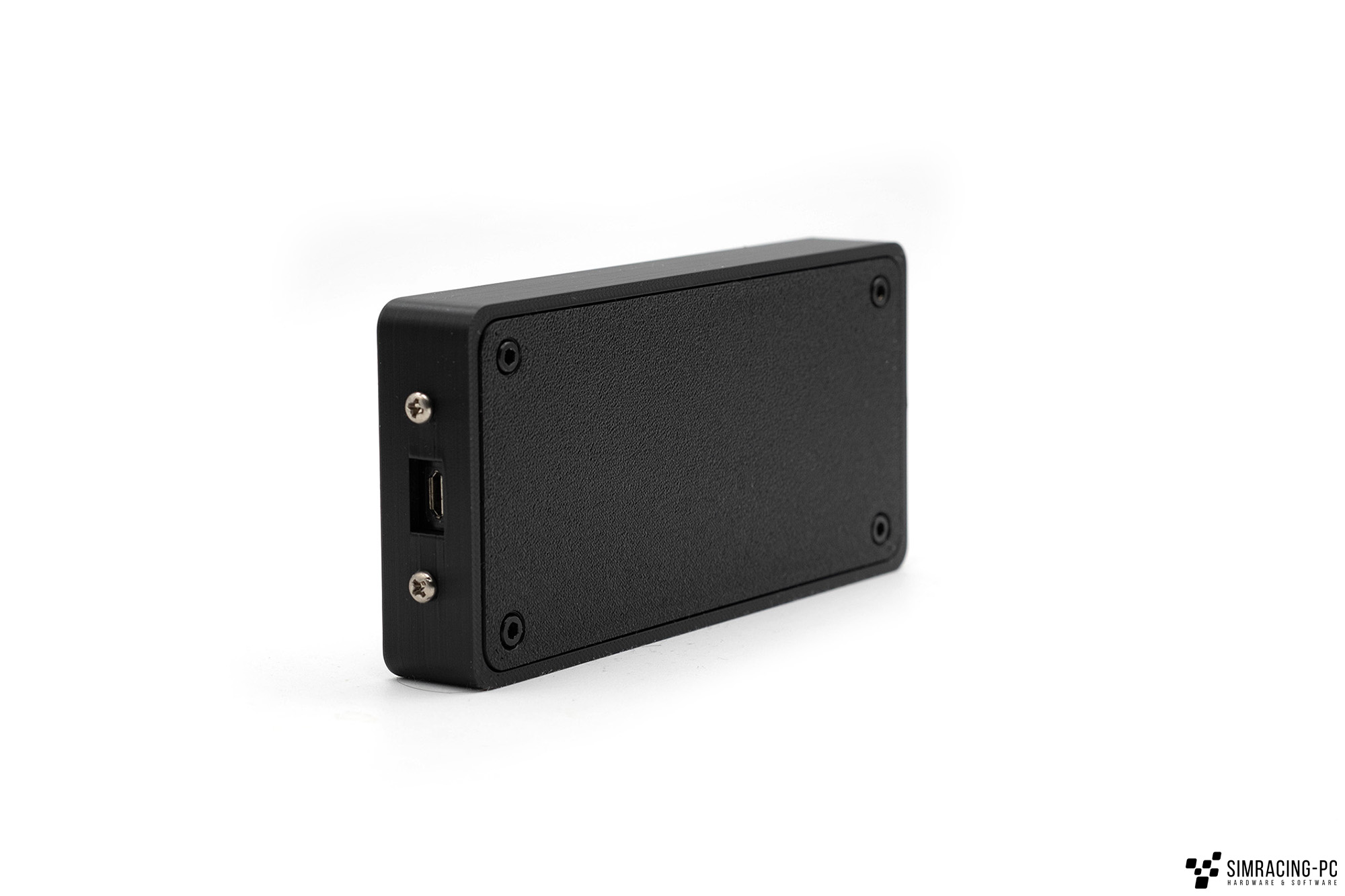
- Screw on the micro USB socket at the front.
- Connect the VoCore display. To relieve some tension from the socket, you can either use a cable tie or fix the USB cable with a hot glue gun. However, as long as the Laptimer is not operated on a moving motion rig, these steps are rather optional.
- Attach the back and tighten the screws. The recess in the cover should point towards the micro-USB socket. Note: Ensure that the three components are correctly aligned before screwing them together.
Overall, assembly is done quickly and should not take much longer than five minutes.

Mounts
The Laptimer weighs only a few grams and can therefore be positioned very flexibly. A holder for aluminium profiles (print file is part of the original project) was used here in combination with Dual Lock adhesive tape strips from 3M (Amazon*).
Alternative components
The project is based on the old version of the 4-inch VoCore display, which was still equipped with a micro USB port. As the newer version has a USB-C connection, there are various possibilities here:
- Installation of a GX12 / GX16 connector as in the original project. However, this requires soldering.
- Install USB-C socket (Amazon*) instead of micro USB socket. The .stl file must then be adapted accordingly.
- 90 degree USB-C to Micro-USB adapter
- Direct connection of the VoCore screen.
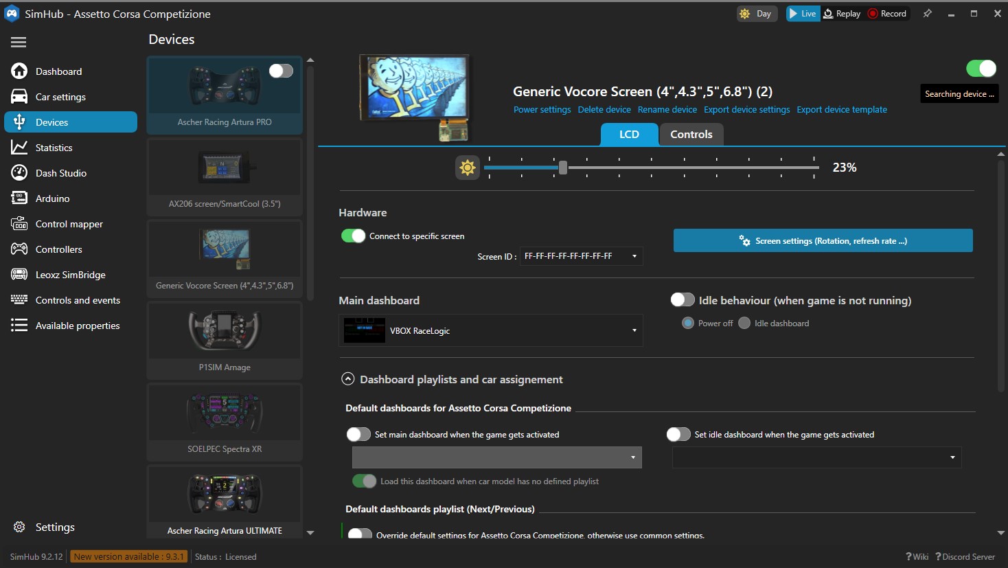
Software (Simhub)
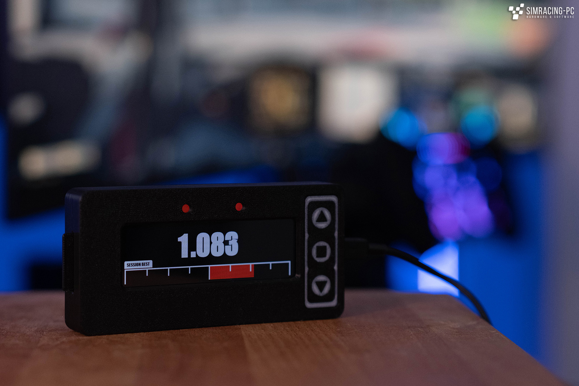
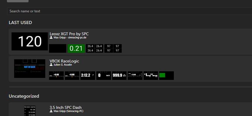
To get the Laptimer up and running, the Simhub software is used as usual, which recognises the VoCore screen (installed drivers required) without any further action. The matching dashboard (file included in the original project) is then selected here, which ensures the functionality of the screen and the simulated LEDs in the cut-out area. The dashboard has various preset pages that can be called up via the display’s touchscreen:
- Welcome Screen
- Gaps
- Delta (Session)
- Delta (All Time)
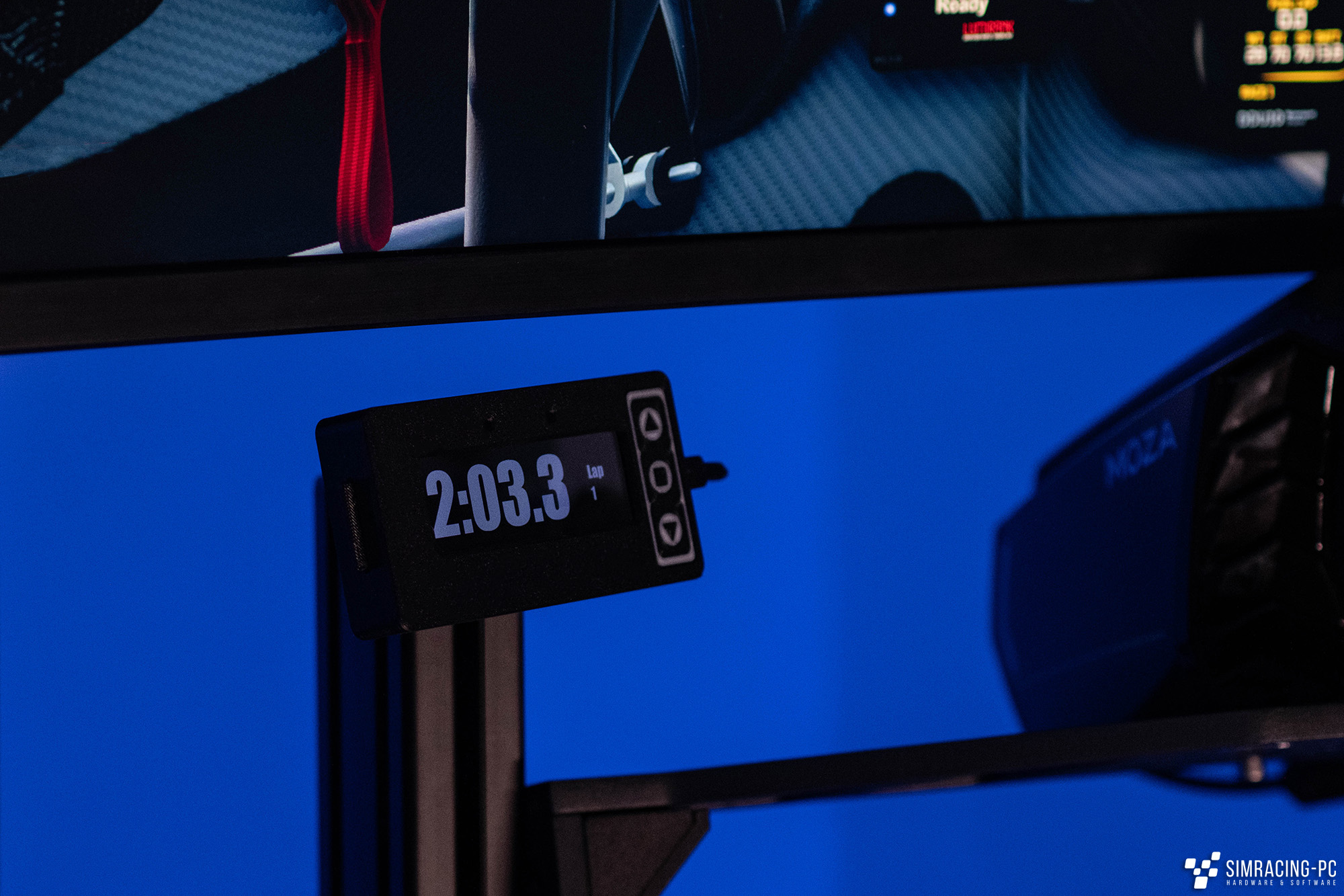
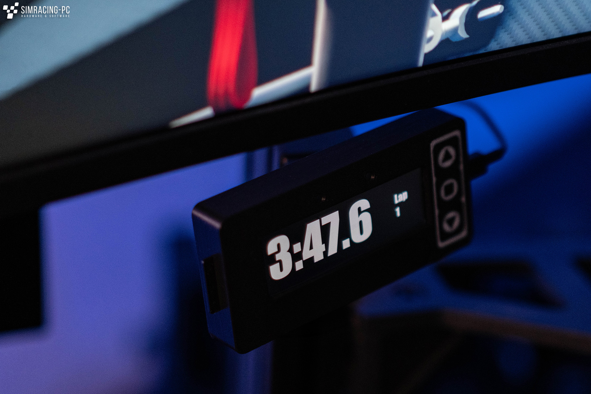
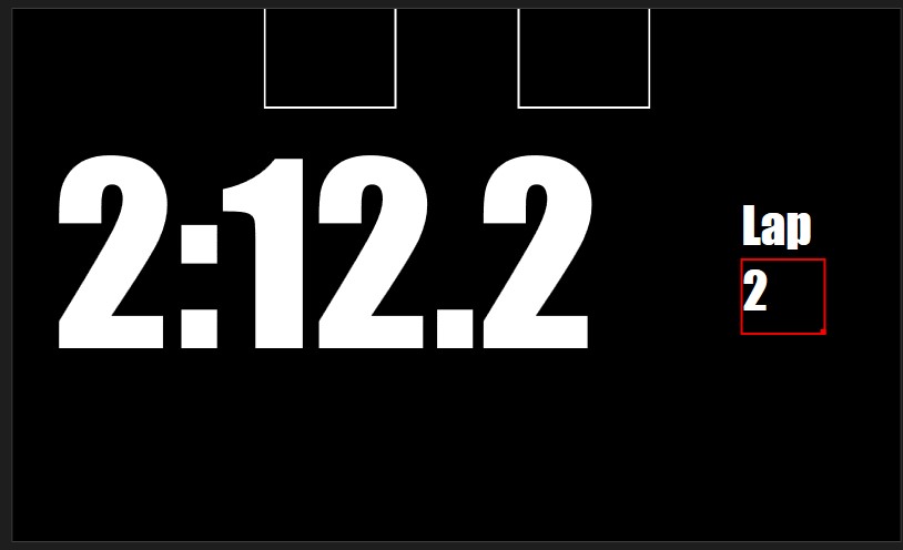
- Lap Timing
- Live Speed
- Max Speed
- G-Force-Meter
- Fuel
- Clipping
Conclusion
The Laptimer is a small but nice DIY project for comparatively little money, which significantly enhances the rig both visually and functionally. It can be built in relatively few steps.


